
FACILITIES
Carbon Capture for Greenhouse Application

The experimental setup is designed to evaluate a bubble column reactor for carbon capture and reuse in greenhouse systems. The main unit is a transparent vertical column, 2 m tall and 100 mm in diameter, partially filled with water. CO₂-rich gas enters through a sparger at the base, producing fine bubbles that rise and transfer CO₂ into the liquid. Natural circulation and multi-phase mixing enhance absorption efficiency.
At the top, a separator removes unabsorbed gases while directing the CO₂-enriched water to storage or direct application. Gas supply is managed with regulators and flow controllers to adjust composition and rate. Probes positioned along the column track dissolved CO₂ levels and temperature, while additional sensors monitor pH, gas hold-up, and circulation.
An automated valve allows pulsating gas injection for dynamic testing, and transparent construction enables direct observation of bubble behavior, complemented by high-speed imaging. Data from all instruments is processed through an integrated acquisition system.
The enriched water can then be supplied to greenhouse irrigation lines, boosting plant growth by increasing carbon availability and linking emission reduction with agricultural productivity.
Airlift Pump Testing Platform

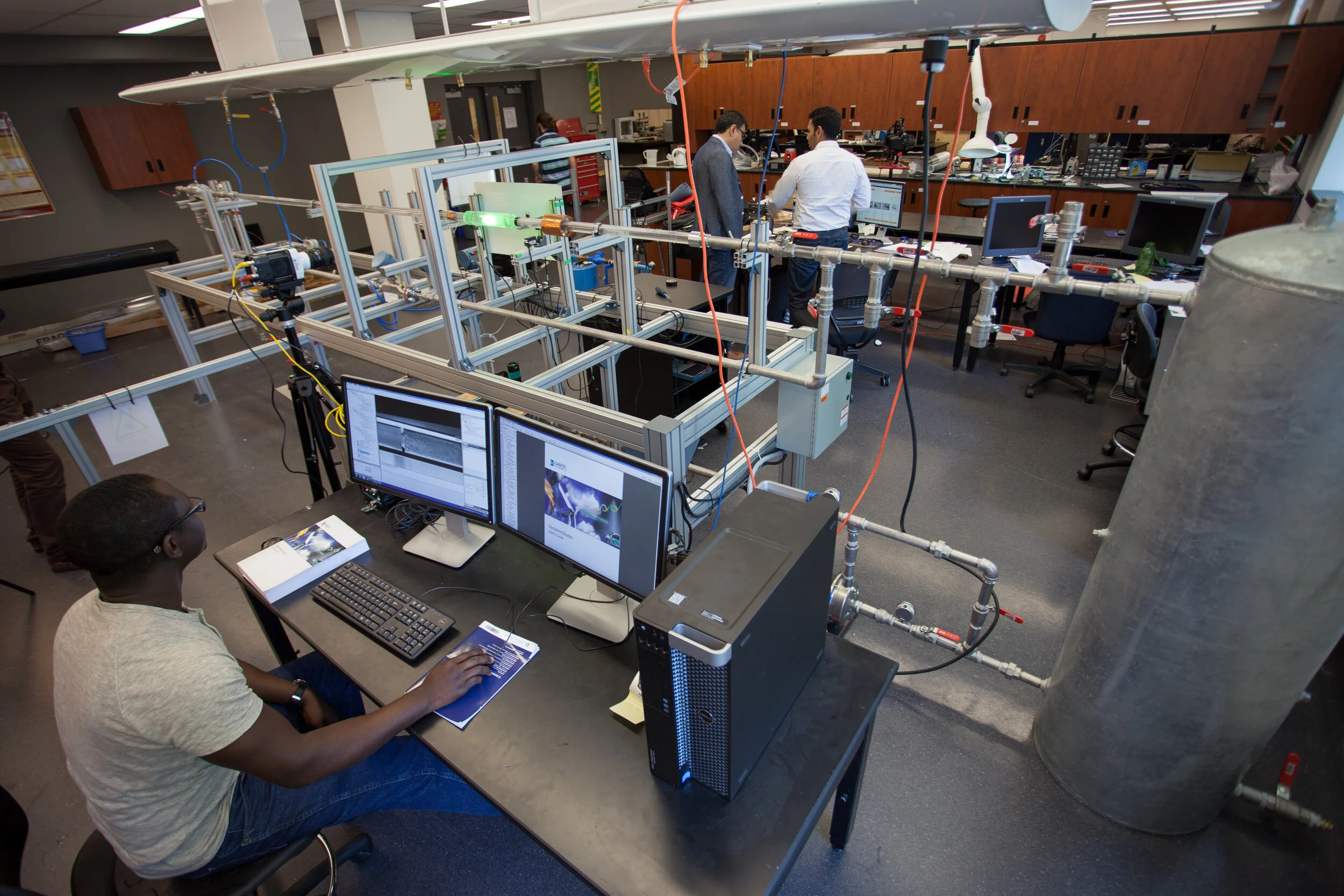
The experimental setup is designed in order to investigate the operation of airlift pumps. The main part of the airlift pump consists of a vertical transparent pipe with a length of 2 m and 31 mm inner diameter. The upper end of the riser is connected to an overhead-collecting tank where the air escapes to atmosphere and water flow return through a down-comer to collecting tank, where water can be measured using a calibrated scale. The overhead tank is designed to direct the water to the collecting tank with minimal fluctuations and damp free vortices and thus provides accurate flow rate measurements.
The movable water supply tank is used to adjust the submergence ratio. All pipes are made of transparent material to allow for the flow patterns visibility. Air flows from the air reservoir and measured by the rotameters and air mass flow control. The flow was visualized downstream of the dual injector using a high speed video camera that can operate at speeds up to 10,000 frames/s. Capacitance sensor is also used to measure void fraction in the pipe riser. The airline is connected to an electrically operated solenoid valve.
The purpose of the solenoid valve is to control the pulsating air stream at various frequencies. The solenoid valve opening and closure is controlled by a cyclic timer. All instruments are connected to DAQ system for data capture and processing.
Two-Phase Flow Test Rig

The continuous inclined air-water pipe flow facility consists of 4 m long transparent Perspex pipes with internal diameters of 24 mm. The pipes are placed on an aluminum frame that can be fixed by a hydraulic system at any angle of inclination, from horizontal position to 30o angle.
When the required inclination is achieved, the frame can be locked by a breaking system for safety reasons. The inclination angle can be measured with high precision by a digital angle level.Water and air are used as working fluids. Water and air supply systems work independently. Water is circulated through the system in a closed loop by a frequency-controlled centrifugal pump with a maximum capacity of 2 m3/h at 30 m total head.
Water is supplied from a 100-liter tank, which is filled with deionized water that underwent filtering through an ion exchanger filter. The loop is equipped with pressure, temperature and void fraction instruments, Coriolis flow meter and Particle Image Velocimeter (PIV) system
High-Temp Air Flow Facility

This facility can be used to test high temperature flow commonly found in energy systems. Currently, the test section simulating the exhaust pipe in the automotive application. The air supplied through high pressure flow blower operating by a variable frequency drive motor to control the air mass flow. 11 KW Leister LHS61 air heater is connected to the bottom of the test section to control the air temperature. Maximum air temperature of 900o K can be achieved in this facility. Local air velocity is measured by Dantec MiniCTA hot wire and the local temperature is measured by thermocouples mounted on a traverse mechanism to acquire the radial temperature distribution. All the instrumentation are connected to the DAQ system.